Wednesday, 12 May 2010

My Blender Process


Model 1:


Model 2:


Model 3:


Model 4:


Model 5:


Wednesday, 14 April 2010

Grease pencil & Blender Boids...What the heck??

How to create a freehand sketch in Blender using a Grease Pencil

  1. View
  2. Grease Pencil
  3. Click on Use Grease Pencil
  4. Draw on the pad
  5. Convert to a Bezier curve
  6. In object mode, Convert to mesh: Alt + C
  7. Tab into edit mode, select all (A) extrude (Z)
  8. Go into side view
  9. click use grease pencil and repeat again (extrude)
  10. Now you have a crazy facade!!
Some cool links on Grease Pencils:

http://www.blendernation.com/grease-pencil-new-feature-on-development/

http://www.blendernation.com/pencil-2d-animation-software/


How to create Boids in Blender to simulate crowds, traffic flow and more!


Inspiration: Filip Zelenka

I stumbled across Architectural visualizer/animator Filip Zelenka who has a unique portfolio including 3D rendering and photography of exemplar designers & architects!
Below is a design of a gallery in Pilsen by designer, Karel Bus, which Filip Zelenka rendered using 3Ds Max.


GREAT PHOTOS OF VARIOUS ARCHITECTURE
Photographs taken by Filip Zelenka


Friday, 9 April 2010

My first Blender animation!


Here's my first attempt at doing an animation in Blender. I made the goblet using a Bezier curve (only one side), then spun it 360 degrees to make the form. I then created a plane over the goblet, & subdived the mesh. After applying the collision and soft body amounts I pressed Alt + A to animate!

Thursday, 8 April 2010

Easter 'Blender' break...

So over the Easter break I attempted a few terrain maps in Blender of the site.
After a few hours my eyes were pretty sore from concentrating and the results aren't that amazing...but I was happy that I'm starting to understand a little more about how Blender operates.

Here are some examples of testing below:

Experiment 1


First I imported a photo of the site into photoshop and created layers according to height/depth. When importing images into blender, black inverts and white rises in height.


I just started with a section of the map to see the result in Blender.
River = black
Land = dark grey
Trees = light grey
Buildings = white

I then imported this into Blender


I abstracted the site by applying different modifers:

WAVE:


BEVEL:


Then I tried adding more 'Noise' in Edit mode


Mesh Deform created an interesting form:


Adding 'Wave'


Experiment 2:

For this experiment I just imported the greyscale version into Blender instead of altering the site map in photoshop. I then applied noise. In object mode added a smooth subsurface.
This terrain is pretty lumpy but it may be ok for rough diagrams.

'


My next experiements will be refining the terrain and adding particle tracing elements and empties.

Tuesday, 6 April 2010

Edni-Brown's "Architecture & Animation"

EDNIE-BROWN, P. (2001) The Will to Animation. In Architecture and animation., ed. B. Fear, 64-73. London: Academy Press

Ednie-Brown's interpretation and reflection on 'the will to animation' was intriguing as he states, "The will to animation is not a matter of rushing out to make things move but a question of the terms through which architecture becomes animate as a technology in itself."

'In order for the will to power to be able to manifest itself it needs to perceive the things it sees and feel, the approach of what is assimilable to it. " (p 66)

Ednie-Brown also refers to experiments he undertook using latex and plaster which resulted in bizarre casts with a variety of finishes. Due to the dynamic variations of force and materials used, Ednie-Brown was able to document a series of animations in form and diagram his understanding of 'the will to animation'. 
"The shift can be tracked across the path from the shower tap to the plaster-cast production, from rigid moulds to flexible ones:" (p 69)

Below is an image of Jessica Lynch's finished drawings


  • Lynch's design evolves through the manipulation of images and patterns in AutoCad
  • Software is experiemented with. A fusion of scientific/mathematical data and abstract design.
  • Lynch's design shows clear documentation of her design process.

Wednesday, 31 March 2010

TUTORIAL Week 6 – 04/04/2010

Create a plane
x enter
Rotate it 90 degrees
click on icon with 3 arrows
Click on fire icon
change emitter to 'hair'
Change normal amount
Add an empty (spherical) and give it a force field
Hair is generated using splines and lines
Segments: 50 is smoother
Visualisation - turn on B-Spline
Select plane
F9 - convert button
Will represent hair as a mesh (convert)
Slash key will isolate what you have selected
Right click plane and move hair to the side
Select 4 dots while holding shift
Press f to make a face


create a sphere
N key = transform properties toolbar
copy name of sphere from the toolbar
change hair back to the emitter system
undervisualisation tab cahnge the first tab to object
OB: (change to sphere)
Run the animation Alt + A

Press the space bar to capture the animation at a particualr point in motion and it should stop.

Tuesday, 30 March 2010

Week 6: Reading Response to Rahim.

This week we were asked to read and respond to two papers by A. Rahim.

(Image A: Rahim, p18, 2006. Residential Housing Tower, Dubai)

RAHIM, A. 2006. 01 Techniques and technology. In Catalytic Formations Architecture and Digital Design, ed. A. Rahim. London: Taylor & Francis.

In this paper, Rahim talks about "unraveling the differences and relationships between often-confused terms such as technology, technique, and technical." (page 2) and how they must be integrated into a 'feedback loop.'

Technology: an application of scientific advance to a cultural context. Is judged qualitatively. Looks at the impact on the user. Can only gain meaning through application.

Technical: is directed towards the efficiency of a mechanical, electrical, or digital operation. Measured numerically.

Technique: Determines the overall outcome of the technology. Method.

Feedback Loop: a two-way transfer of information-between a technical innovation and its context.

I found the section on Danish architect and designer Verner Panton was very interesting as Panton used science and experimentation to achieve a new technique in design with his stackable, cantilevered plywood chair for the WK European Furniture Design Competition and from there continued to experiment with finding newer, lighter materials to work with.

By embracing technology, being curious and exploring various techniques Panto was able to come up with unique designs and techniques. Panton was also inspired by his immediate cultural context which at that time was Pop Art and mass production.
As a designer I can look at my surrounds and current technology to discover new materials and also cultivate a technological design practice.


(Verner Panton's Prototype Wooden S-Chair.
Designed by Verner Panton for Thonet, Germany. 1960. Beech plywood.)


RAHIM, A. 2006. 05 Migrating coastlines. In Catalytic Formations Architecture and Digital Design, ed. A. Rahim. London: Taylor & Francis.
 

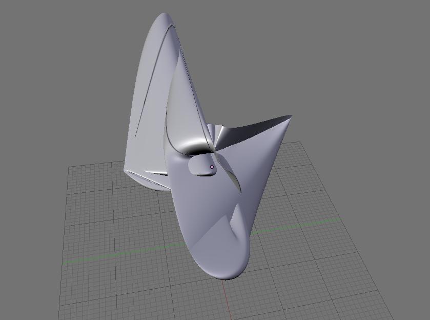
Rahim reviews the Residential Housing Tower in Dubai. (UAE, 2004)

"The 45-story, 450,000-square-foot residential tower overlooks the city of Dubai and the Arabian Gulf on one side and the desert on the other." (page 1)
(Image B: Rahim, p6, 2006)

(Image C: Rahim, p24, 2006)

I love the organic structure of this residential housing building in Dubai as it is such a fluid structure with a sense of movement. The systematic approach towards the design and experimentation process was also a very useful way of incorporating technology and current context together:
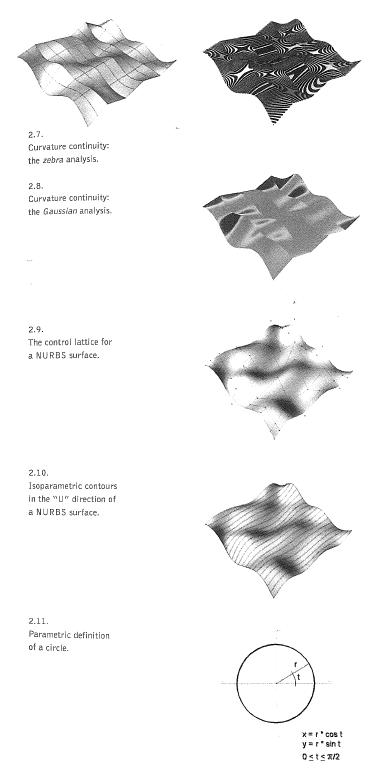
  • Various pressure modulated in a feedback loop
  • Generating a flow to activate the centre
  • Twisting particles create the structural form
  • Organisational patterns

Wednesday, 24 March 2010

Inspiration


TUTORIAL Week 5 – 25/03/2010

BLENDER SESSION 'How to render an image and save in Blender'

Placing image onto a surface (google)

Save image of the site view onto desktop (3600 x 3600 is the limit - or default)

In blender:
  • Right click on edge of screen - split screen - f12 to render
  • delete cube

  • Space bar - Add mesh - plane
  • press n
  • set at zero
  • enter ratio into X & Y coordinates of the size of your image (eg 1.196 x .810)
  • tap into edit mode
  • toggle 'a' key (selects all or none of the vertices in the object)
  • press 'u' key
  • click unwrap
  • click on hash (3DVIEW) icon on tool bar and change to UV MAP
  • Click on image - open
  • open map image from the desktop
  • press tab
  • press material icon (silver ball)
  • add new
  • Click on 'texface'
  • click on orange box icon - change to 'textured view'
  • (shortcut: Ctl + up arrow)
  • change from 'global' to 'local'
  • right click on camera & move it so there is a good view of the image from above
  • if there are problems setting the camera, make all axis zero, then hold 'x' & 'r' to rotate camera on the axis
  • 'z' &'r' until view is great
  • press f12 to render
  • f3 to save
  • enter file name to save jpeg
  • press f10 to get into scene
  • click 'HD' for high definition render
  • f3 save
  • experiement with lighting - change from 'local' to 'global'
  • f12 - you can see the lighting is now darker
  • NOW create a plane to it shoots particles across the storey bridge
  • then add a series of forces fields around the scene
  • 'shift' + 'middle mouse button' to move image around the screen
  • rotate plane 'r' + 'x' press 90(for degrees) then enter
  • move plane down so that it sits as cloesly to the image as possible
  • then click on fire icon
  • add new
  • then change 'end' & 'life' to 250
  • change normal speed to 200
  • press 'alt' and 'a' to animate

Tuesday, 23 March 2010

Kolarevic's "Architecture in the Digital Age: Design and Manufacturing"

Today I read and reflected on the weekly reading by Kolarvic. (2003)

NURBS - PARAMETICS - DYNAMIC & FIELDS OF FORCES - DATASCAPES - METAMOPHASIS - PERFOMATIVE ARCHITECTURE

KOLAREVIC, B. 2003. Introduction. In Architecture in the Digital Age: Design and Manufacturing, ed. B. Kolarevic, 13-28. New York: Spon Press.

Kolarevic speaks about the changes in the conceptualization of architectural forms over the centuries due to advancements in technology in a mind-opening way. Today, digital technology is not only being used as a representational tool but as a way to derive the form, generating design outcomes based on algorithms and "the chosen generative computational method." This means that the age-old method of intuitive freehand drawing and an emotive response to the site and its users is replaced with a matrix style set of outcomes. As an emerging Architect this is exciting but poses a few questions at the same time. Will buildings lose their soul?

(Image1: Diagrams of Parameters, Kolarevic page 17)

"The parametric description of forms (parametrics) provides a particularly versatile way to represent complex curves and surfaces. Sets of equations are used to express certain quantities as explicit functions of a number of variables, i.e. parameters, which can be independent or dependent." (Kolarevi, p17)


(Image2: Diagrams of Waterloo Station, Kolarevic page 19)

It was really interesting to read about the design of the International Terminal at Waterloo station, where architect, Greg Lynn, uses 'force' and 'motion' to evolve a form with animation software. The result is a fluid structure.

"Lynn utilizes an entire repertoire of motion-based modeling techniques, such as keyframe animation, forward and inverse kinematics, dynamics (force fields), and particle emission." (Kolarevic, p19)

Monday, 22 March 2010

TUTORIAL Week 4 – 18/03/2010


This week our tutorial group covered Blender Particle Systems:

We were shown how to set up 'fields' and 'emitters' in Blender that create an animation effect which simulates various forces on an object. This is relevant as it can be used to determine the effect of elements such as wind, water, sunlight, onto a building as well as create surprising design options based on mathematics and physics. 
By placing an object as an emitter (we used the standard 'monkey head' as you can see in my experiements below - 1 & 2) you place various 'empties' around the object and assign a field. The result is particles shooting out and off of the object. The weekly readings were an interesting support material to the logic behind using Blender as a design tool.

*Image found at Blender Nation

Reflection on the Readings:

ROOSENDAAL, T., HESS, R. & BLENDER FOUNDATION. 2007. The essential Blender : guide to 3D creation with the open source suite Blender. San Francisco, CA: No Starch Press.


(Image of water drop, accessed March 18)

I found this reading particularly interesting as it caused me to reflect on the positive and negative aspects of using computer software to determine a design based on mathematics and science rather than intuitive freehand sketching.


“Often, as in the case of water splashing into a glass, a computer can do a much better job of animation than a human being can, because it can actually simulate the physics of the situation. The same applies to a falling wall of blocks or a flag flapping in the wind. Since these are physical simulations, you have to tell your CG application the basics about what you're simulating, which usually include values for gravity, elasticity, mass, wind, etc.” (p.27)


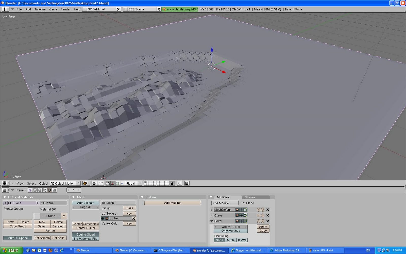
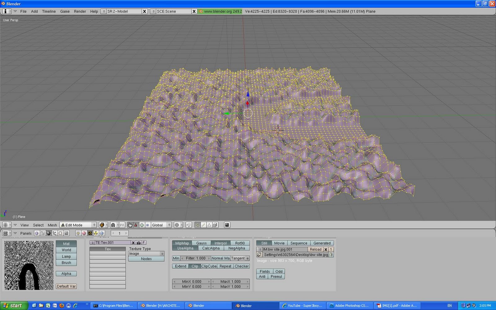
“Rigid Body Physics' a block wall in mid-tumble. Fluid Simulation: Water pouring into a glass & Soft Body Physics: A flag in the wind.”
(Image of Australian Flag, accessed March 18)


WATANABE, M. S. 2002. The first generation: design as science. In Induction Design: A Method for Evolutionary Design, ed. M. S. Watanabe, 24-35. Basel: Birkhäuser.


__________________________________________

Our tutor, Florian Heise, showed us an example of his work that incorporated 4D Diagramming:

Review of Florian’s final design:

• Inspiration based on nature. Forces, gravity, emergence
• Grass waving in the wind
• Blender animation of the globe spinning showing communication via technology
• Emergent design manifesto: design takes place in a global context, aim to explore the potential of emergence
• Emergence: refers to the way complex systems and patterns arise from shape interactions
• Looking at water molecules that interact in a certain way to create an outcome (ice, skin on water, splashing etc)
• Freemind program on the internet to make mind maps
• Looking at global system affecters (building and site comparison)
• Developed nations comparison
• City size comparison – Urban density
• Precedent Series: Cellular automata – Wolfram
• Generative systems: John Frazer (a building evolving over time)
• H2 House + Embryological House – Lynn
• Cardiff Bay Opera House – Lynn
• Gades computer program – Bentley
• Particle tracing
• Zebra surface analysis
• Wind analysis
• Floor plate dissection
• Particles using floor plates and vectors
• Flyaround and rapid prototype model
• All diagrams/models in Cinema 4D
• Thesis reflection
• Explain the process in detail for the outcome


INSTALL PYTHON 2.6 http://www.python.org/ (is compatible with Blender)


GROUP: BLENDERAMA

In response to Project 1A, being the individual site analysis of the Howard Smith Wharves, we formed groups and discussed our individual analysis of the site. Our group, is Blenderama, consisting of Marita, Libby and I.
The Final Project 1B design outcome:
  1. Type of Building: Multi-use community space
  2. Public transport infrastructure - Ferry Terminal
  3. An outdoor aspect
To be included:

• Do a nolli map of site
• Do a figure diagram
• Look at site from a large scale (kangaroo point 1:1000)
• Do an accurate suburban plan


PROCESS USING BLENDER: